
Nothing is more frustrating than low-voltage troubleshooting when it’s hot, the calls are piling up, and you’re getting home just in time for bed. Or choosing to sleep in the truck as the on-call technician. I remember those days, and while I might not have that anymore, providing tech support at Arzel reminds me that low voltage is still one of the most problematic areas for technicians.
Being more effective in troubleshooting low-voltage circuits helps everyone, from the homeowner to the factory tech support. Mainly it helps you to do your job better, with happier customers. With that in mind, here are some tips to help you or someone you know.
Resistance tests quality; continuity doesn’t. One of the most valuable lessons I’ve learned is to check resistance, or ohms (Ω). As HVAC technicians, we work mostly with switches that are automated by different parameters. This circuit engages that circuit, this circuit is temperature controlled, this one is draft controlled, this one is pressure controlled. Every low voltage circuit has a hot and a common or neutral. Power flows from hot to ground, powering the circuits it passes through. Testing the resistance in these circuits should be the first step in low-voltage troubleshooting.
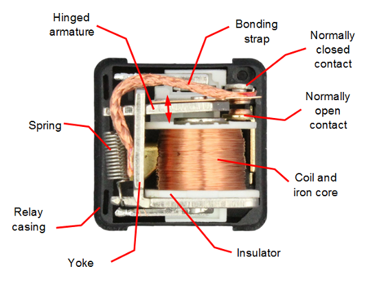
Before you begin low-voltage troubleshooting, make sure you know how the circuits work. See the diagram for a visual example. When the coil is energized, the normally open contact is pulled closed, and the normally closed contact opens. The circuit can be tested for resistance by checking between the contacts “Common” and the NC or NO terminals. If the contact is open, you should read OL or ∞. If the contact is closed, you should see less than 1Ω of resistance.
Most everything in the low voltage circuit of the HVAC system is controlled by a series of these contact points. The thermostat has a bank of relays, zoning panels have a bank of relays, and the furnace circuit board has many relays. The outdoor unit has contactors which are functionally the same as relays but are typically rated for a higher current. Even safety switches, like the high and low pressure switches in the outdoor unit are simply a closed contact point. Draft switches on an inducer motor are normally open, and then close when sufficient draft is proven. It is important to know how these components work because then we can be certain whether they are good or bad. And it is always better to know than to make assumptions.
We’re going to focus on a thermostat for this blog, but testing a contact is functionally the same, no matter the device.
There are pins on the back of a thermostat, and the relays make a connection between R and the heating or cooling operation (W1, W2, Y1, Y2, G, O). Calls for operation depend on whether we have a heat pump or an air conditioner, and also whether the HVAC equipment is single stage or two stage.
Let’s look at the most basic operation. A call for heating makes a connection between R and W. A call for cooling connects R, Y, and G. If the thermostat has batteries, locate the pin for R and the pin for W, Y, or G. Those contacts can be tested to verify that the thermostat is outputting heating or cooling. If R-W is greater than 1Ω and the thermostat is calling for heating, then the thermostat is bad. The same is true for R-YG. If you measure greater than 1Ω of resistance in that connection, and the thermostat is calling for cooling, then you know that the thermostat is bad.
Never assume a new thermostat is good if the system isn’t working. In tech support here at Arzel Zoning, we’ve been on the phone with technicians who assumed the thermostat they just installed was working correctly. But when they tested the resistance, they proved that the thermostat was DOA. Assumptions can waste time and make those summer days a lot longer than they need to be.
Testing resistance is the surest way to prove a circuit, but it isn’t always possible. Testing resistance requires one side of the circuit to be disconnected so we’re only testing the contact point, not the entire circuit. If testing resistance isn’t feasible, the next best way is to test the voltage.
When testing voltage you need to check in a few places. (Make sure you do this! Neglecting it could send you on a wild goose chase.)
This testing sequence works for high-voltage circuits as well. And here’s a pro-tip for the contactor in the outdoor unit: if you have greater than a 1vac difference between the incoming and outgoing side of the contactor it’s time to recommend replacement. The contacts are burned or pitted. For example, you might read 238.6vac in and 237.6vac out.
By testing both directions you can move past assumptions and know for certain if something is contributing to the problem you’re there to diagnose.
In addition to testing relays, you’ll need to know the sequence of operation. Test the system from point A to point Z, ruling out components one at a time until you arrive at the cause of failure. This approach will save you a lot of frustration. And when the schedule is slammed, it will also optimize your time by saving you callbacks.
As a last note, get a decent meter! There’s nothing more frustrating than using a meter that has more functions than necessary. Or one that’s not made for the application. True RMS meters are necessary.
This isn’t a paid promotion but my current meter is the Fieldpiece SC440. I’ve used Fieldpiece for nearly 20 years. They are simple, reliable, and have all the functions necessary for the HVAC tech. Today as a factory technician I rarely need to guess if the Fieldpiece guys have their meter set to the correct function.
Written by JR, Arzel Tech Support
How Many Stages Can the Pro Panel Control? The Pro Panel can handle up to two stages of cooling and up to four stages of heating. It can control multi-stage furnaces, air conditioners, and heat pumps. For example, it can control a two-stage heat pump with two stages of electric heat strips. Or it can […]

The Pro Panel is a universal zoning system. That means it can control every type of equipment: conventional furnace and air conditioner, split and package geothermal, heat pump, dual-fuel systems, and all-electric systems. The Pro Panel works with multi-stage equipment too, up to 4 stages of heat and 2 stages of cooling. We worked to […]
There are three main steps to installing a Pro Panel zone control system: Install the dampers and tubing. Install the panel and thermostats. Connect to the Arzel Pro app to configure the Pro Panel for your installation. After you complete these three steps, your customer will feel the difference immediately. This is one of our […]
Our new Pro Panel control can zone up to 16 zones. That’s twice as many as our biggest AirBoss, and four times what our HeatPumPro can do. With 16 zones possible, the Pro Panel can be a zoning solution for more light commercial buildings and large houses. On top of the additional zones that are […]